THERMODYNAMIC STEAM TRAP - HOW IT WORKS
|
|
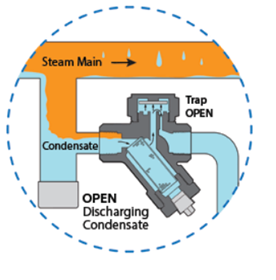
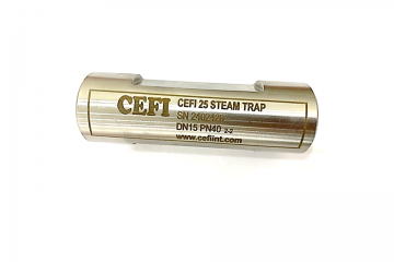
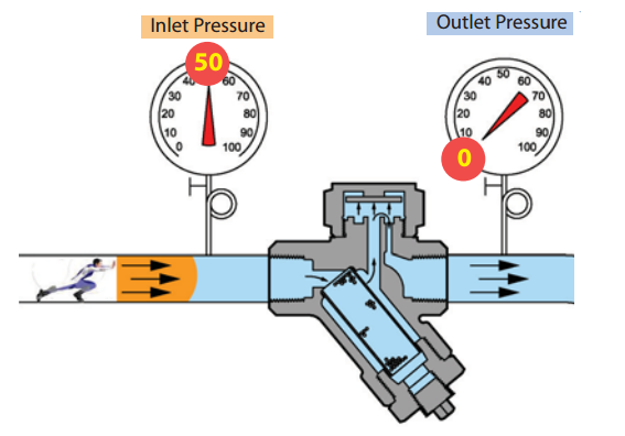
Thermodynamic Steam Trap Thermodynamic traps have only one moving part, the valve disc, which allows condensate to be discharged when present and closes tightly upon the arrival of steam. These traps have an inherently rugged design and are commonly used as drip traps on steam mains and supply lines. Their solid construction and single moving part make them resistant to waterhammer and are freeze-proof when installed vertically. Thermodynamic traps will only discharge small amounts of air and therefore are typically not used in process applications |
|
|
Valve Disc Open
When condensate is present, trap remains in the open position allowing condensate to discharge. Steam pressure pushes the condensate thru the trap. |
|
|
Valve Disc Starting to Close When steam enters the trap, it creates an internal pressure above the disc that instantly forces the disc and seat to close tightly, preventing steam from escaping. |
|
|
Valve Disc Closed Steam pressure above the disc holds the disc closed, trapping steam in the system. Trap will remain closed until the steam above the disc condenses, due to heat loss through the cap. |
Related posts
-
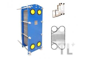
TL Plus offers a wide range of plate heat exchangers with robust, optimized gaskets in a compact and energy-efficient frame design. Plate heat exchangers are suitable for a wide range of industries and applications from heating, cooling and heat recovery to condensation and evaporation. The design of the corrugated plates optimizes heat transfer, providing a large yet compact surface area so that heat can be transferred from one liquid or gas to another. The plates are designed in a corrugated herringbone pattern, creating ideal turbulent flow and depending on the pressure drop of each application. The plate heat exchanger design optimizes flow distribution, reduces fouling and uneven temperature zones, maintaining high performance levels over time without unnecessary energy loss, maintenance costs or unexpected downtime. The plates are designed with optimum pressing depth, V-shaped corners and various corrugated shapes, all carefully designed and selected for optimum performance - depending on the application, each product line has its own plate features. Special benefits from our tecnology: A short pay-back period on investment. High thermal efficiency Compact design and simple installation Each heat exchanger is individually designed for the heat load, flow rate and pressure drop limitations of the specific application. Energy efficiency solutions has the power to protect the environment and create greener solutions. Specifications Connections from DN25 to DN400 (design standard PED 2014/68/EU (EN13445) and ASME sec VIII, Div. 1) Plate material: AISI 304/316, titanium, SMO. Other materials available on request Gasket material: EPDM, NBR and Viton. Plate height up to 3.5 m Flow rate up to 7200 m³/h (31,700 gpm) Working pressure up to 25 bar (363 psi) Applications HVAC industry such as seawater and groundwater cooling solutions, solar heating solutions, saturated steam or other existing energy sources. Marine/offshore industry such as central and lubricating oil cooling Dairy/food/beverage industry such as pasteurization, heat recovery and other light duty applications Sugar industry Biogas industry Pulp and paper industry Heavy industry Mining industry Petrochemical industry Chemical industry such as waste heat recovery from condensate
-
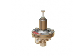
All equipment has a maximum working pressure value, if the working pressure of the equipment is lower than the supply pressure of the system, we need to reduce the system pressure before entering the equipment. In case the pressure reducing valve cannot work, the pressure exceeds the threshold, there will be a safety valve to release the pressure to protect the equipment. For saturated steam systems, most boilers are designed to work at high pressure, usually cannot run at low pressure because the generated steam will be humid, low pressure requires pipes with a large enough size to meet the flowrate. Therefore, the system will operate more efficiently and economically when the steam is generated at high pressure and then reduced before entering the equipment for use. For design calculations, heating applications, from the saturated steam pressure we will deduce the temperature, from which we can choose the appropriate pressure value to calculate the application. Benefits of using saturated steam at low pressure: - Low pressure steam has higher energy than high pressure steam - The amount of flash steam produced will be less, so the energy loss from flash steam will be lower.
-
-
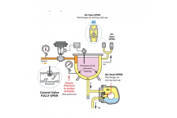
EFFECTS OF AIR IN A SATURATED STEAM SYSTEM During operation of the saturated steam system, air flows from outside enter to inside the steam system when the system stops working, from the water supply system, from the vacuum breaker valve. The presence of air in the steam system greatly affects the heat exchange process because air can form an insulating layer on the heat transfer surface, the thermal conductivity of air is 25 times worse than thermal conductivity of water. Therefore, removing air through the THERMOSTATIC AIR VENT is necessary. The THERMOSTATIC AIR VENT needs to be installed in the appropriate location and pay close attention to the most effective air release.
-
-
-
-
Copyright © 2020 Technical TL +


